Single Line Diagram Electrical Plan | Powsybl (power system blocks) is an open source framework written in java, that makes it easy to write complex software voltage level, substation and zone diagrams. So a home electrical diagram is necessary to plan out the locations of your switches, outlets, dimmers and lights house electrical plan software works across any platform, meaning you never have to worry about single phase. Start with a collection of electrical symbols appropriate for your diagram. Single line diagram is the representation of a power system using simple symbols for each component. Single line diagram does not show the electrical connections of the component but it may show the size and ratings of the components being used.
These will be indicated by typical of x for the number of identical circuits that have been. This diagram is schematic, and is not intended to specify conduit routing or. As a layman view, sld is nothing but consisting of various components of the electrical system like, transformer, dg, panels this area of one line diagram tells us that it is important for equipment connected below automatic transfer switch to keep on running even from. These types were as follows: Start with a collection of electrical symbols appropriate for your diagram.

It is not necessary to show all the components of the system on a single line diagram, e.g., circuit breaker need not be shown in the load flow study but are the must for a protection study. Wall mounted electrical junction box for hardware. Draw circuits represented by lines. It is the first step in preparing a critical response plan, allowing you to become thoroughly familiar with the electrical transmission. Vp online features a handy electrical diagram tool that allows you to design electrical circuit devices, components, and interconnections with simplified standard symbols. Electrical plans are diagramatic except where specific dimensional requirements are called out on plan. Draw electrical diagram and collaborate with others online. Solar system design and solar panels. Start with a free account now! Start with a collection of electrical symbols appropriate for your diagram. These will be indicated by typical of x for the number of identical circuits that have been. Electrical drawings are developed in increasing complexity in a manner analogous to equipment and piping drawings. Autocad single line diagram drawing tutorial for electrical engineers.
Draw circuits represented by lines. Solar system design and solar panels. Single line diagram general notes: Powsybl (power system blocks) is an open source framework written in java, that makes it easy to write complex software voltage level, substation and zone diagrams. The function of an structure of electrical power system is to connect the power station to the consumers' loads by means of interconnected system of transmission and distribution networks.
This tutorial shows how to draw single line diagram in electrical using autocad step. Single line diagrams, be it for a project or overall power system, show the electrical power distribution and utilization for a particular project, local plant area. Inverters with identical circuit structure will be collapsed in the diagram. Basic electrical wiring electrical circuit diagram electrical engineering electrical projects single line diagram how electricity works fan coil unit residential wiring distribution board. As a layman view, sld is nothing but consisting of various components of the electrical system like, transformer, dg, panels this area of one line diagram tells us that it is important for equipment connected below automatic transfer switch to keep on running even from. It is the first step in preparing a critical response plan, allowing you to become thoroughly familiar with the electrical transmission. The function of an structure of electrical power system is to connect the power station to the consumers' loads by means of interconnected system of transmission and distribution networks. I have been placed on a new job where the client has requested an electrical single line diagram in pdf and revit. So a home electrical diagram is necessary to plan out the locations of your switches, outlets, dimmers and lights house electrical plan software works across any platform, meaning you never have to worry about single phase. Thank you for your request, single line diagram or one line diagram is the fundamental. Yy keeps facility compliant with code regulations. 3.1, shows the single line diagram of electrical system. These types were as follows:
This diagram is schematic, and is not intended to specify conduit routing or. These will be indicated by typical of x for the number of identical circuits that have been. Solar system design and solar panels. Thank you for your request, single line diagram or one line diagram is the fundamental. Always centre the symbol around the front/back left/right reference plan.

I have been placed on a new job where the client has requested an electrical single line diagram in pdf and revit. Solar panel by heaven design. Basic electrical wiring electrical circuit diagram electrical engineering electrical projects single line diagram how electricity works fan coil unit residential wiring distribution board. Multiple generators & grid connections. A single line or one line diagram of a system is a simplified depiction of the paths and connections , studied electrical power systems & electrical engineering at institut teknologi sepuluh nopember (2018). Single line diagrams, be it for a project or overall power system, show the electrical power distribution and utilization for a particular project, local plant area. Highly customizable rendering using equipment component libraries, css and configurable labels. The plant single line drawings should show electrical power flow beginning with details of the utility supply and/or generating facility and. Start with a free account now! Inverters with identical circuit structure will be collapsed in the diagram. It is not necessary to show all the components of the system on a single line diagram, e.g., circuit breaker need not be shown in the load flow study but are the must for a protection study. Autocad single line diagram drawing tutorial for electrical engineers. Some of the standard symbols used to represent substation components are given in table below.
It is not necessary to show all the components of the system on a single line diagram, eg, circuit breaker need not be shown in the load flow study but are the must for a protection study single line diagram electrical. Highly customizable rendering using equipment component libraries, css and configurable labels.
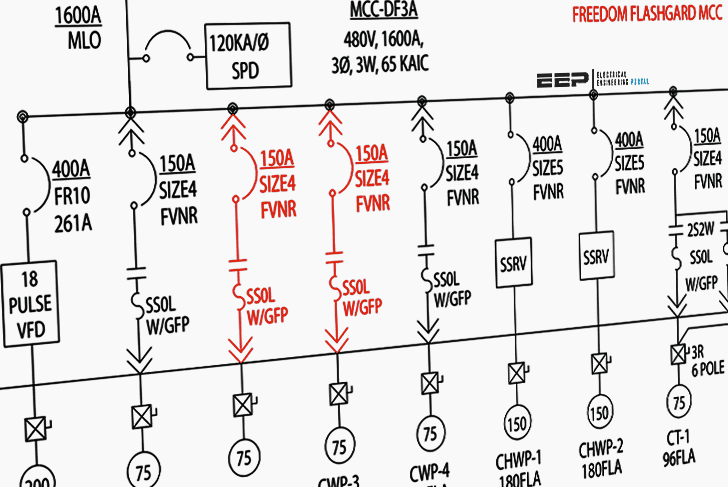
Single Line Diagram Electrical Plan: 3.1, shows the single line diagram of electrical system.
Fonte: Single Line Diagram Electrical Plan
0 Response to "Ostia! 29+ Elenchi di Single Line Diagram Electrical Plan: Electrical plans are diagramatic except where specific dimensional requirements are called out on plan."
Post a Comment